Ringallets — Process
From PLA prototype to a sand-cast aluminum ring with milled and water-jet legs. Six steps, one design pivot, and a CA who couldn't wait to test it.
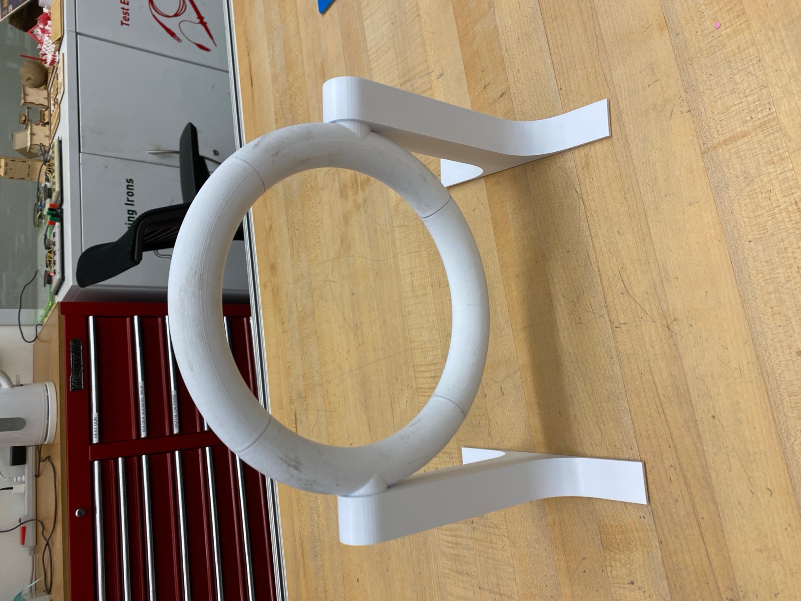
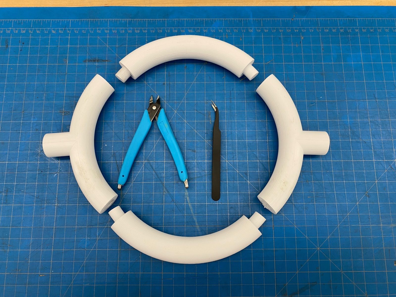
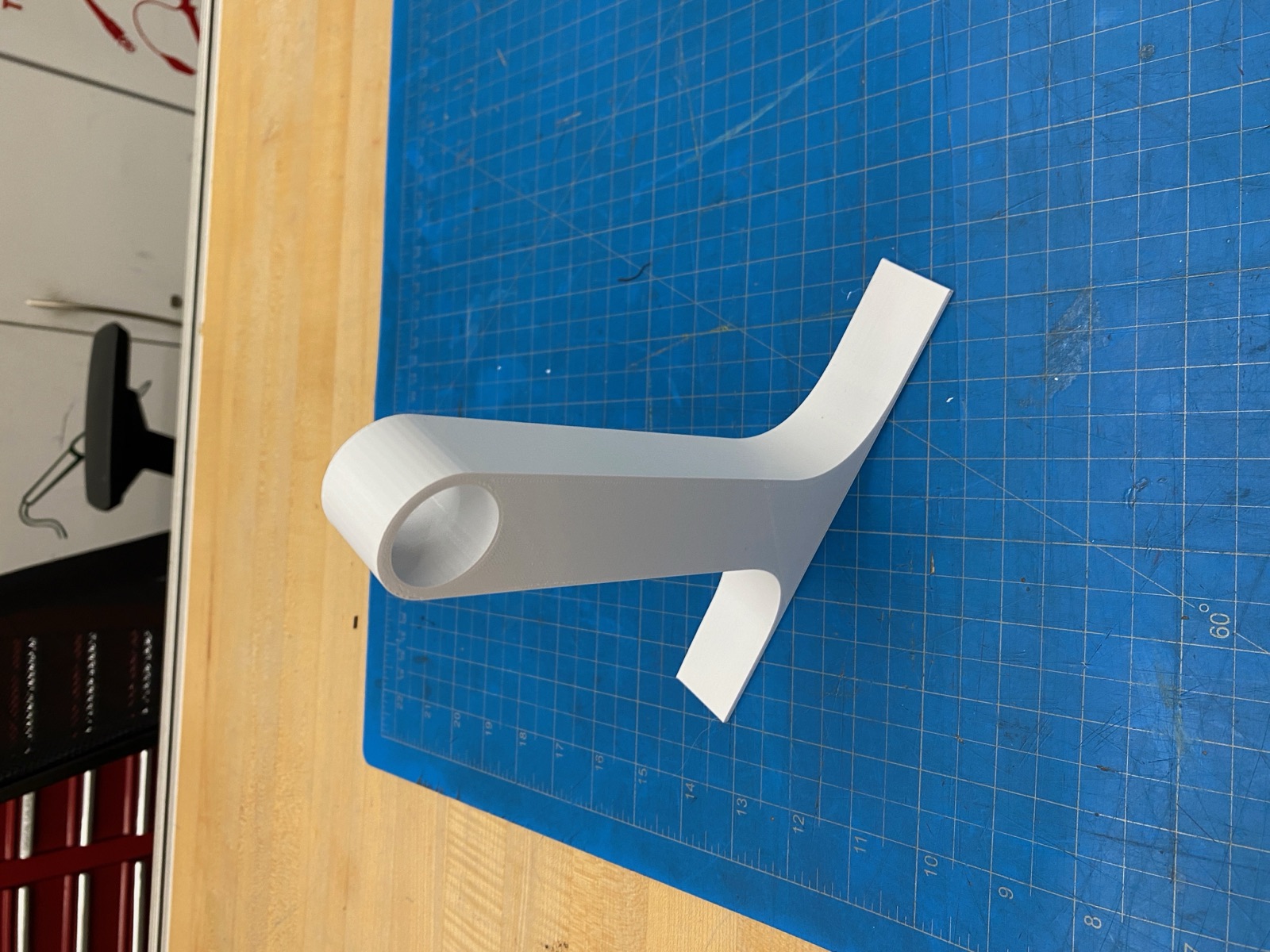
1. PLA Prototype (v1)
The first version was 3D printed in PLA. The ring was modeled as four quarter-circles that friction-fit at their joints, with two of those quarters carrying integrated round pegs. The legs printed as flat plates with round holes to receive the pegs. This was a faithful proof-of-concept of the assembly idea before committing to aluminum.
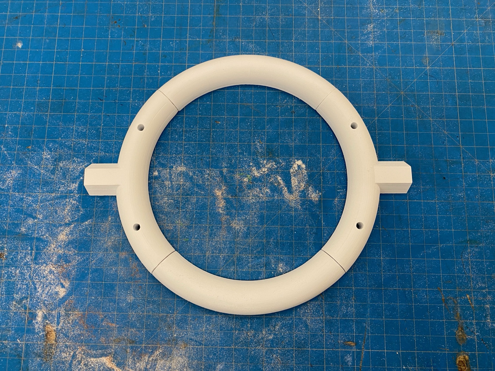
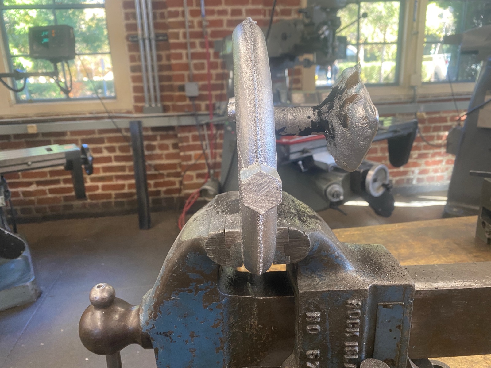
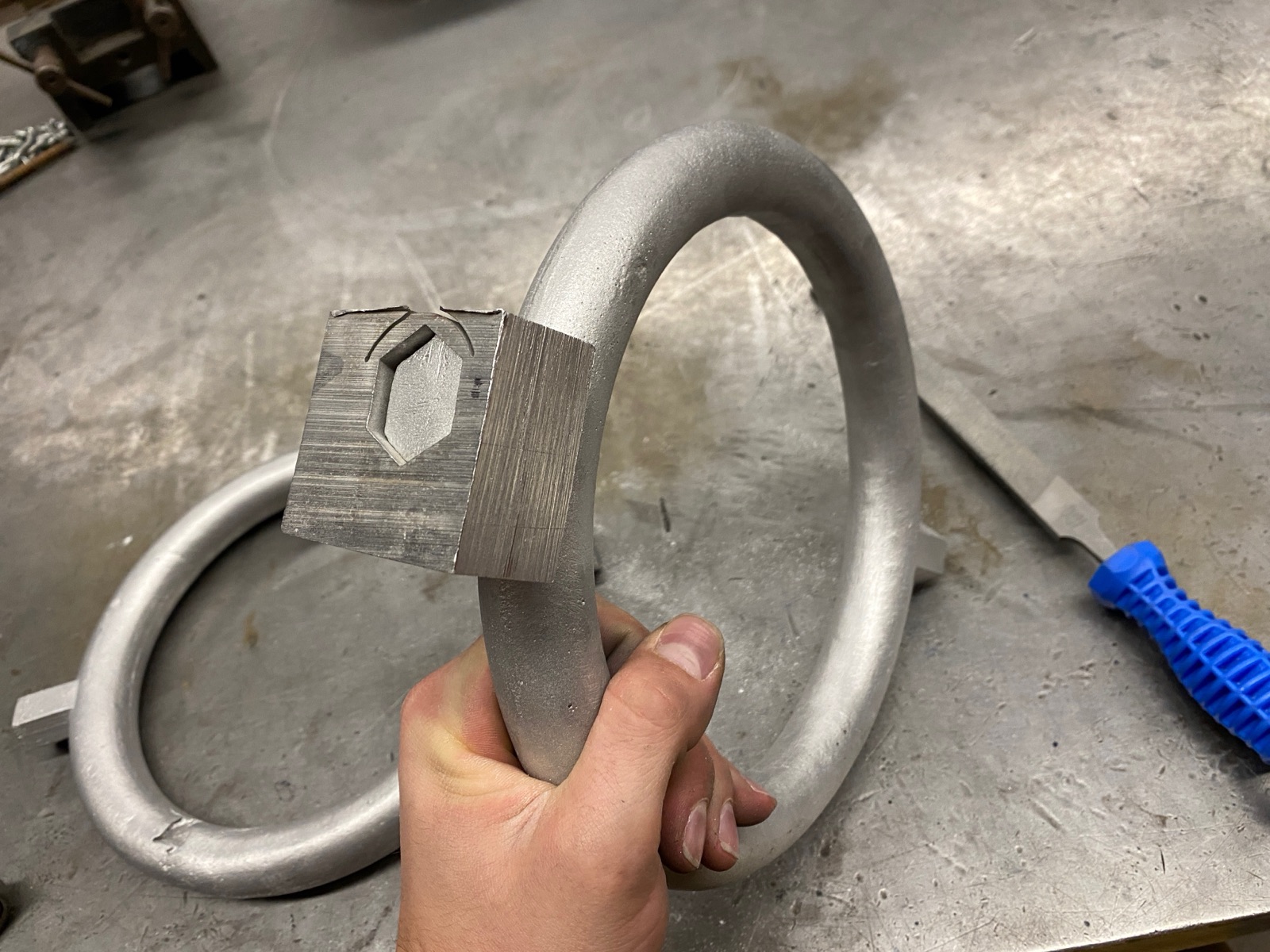
2. The Hex Pivot
Round pegs let the ring rotate freely in the leg sockets. If the friction fit wasn't perfect — and at PLA tolerances, it never was — the ring wobbled side to side under load. Switching to a hex cross-section killed the rotational degree of freedom outright: a hex peg can't spin in a hex hole, even with measurable clearance. The hex also made the joint more forgiving on tolerance, since the flats engage at six points instead of relying on a tight diametric fit.
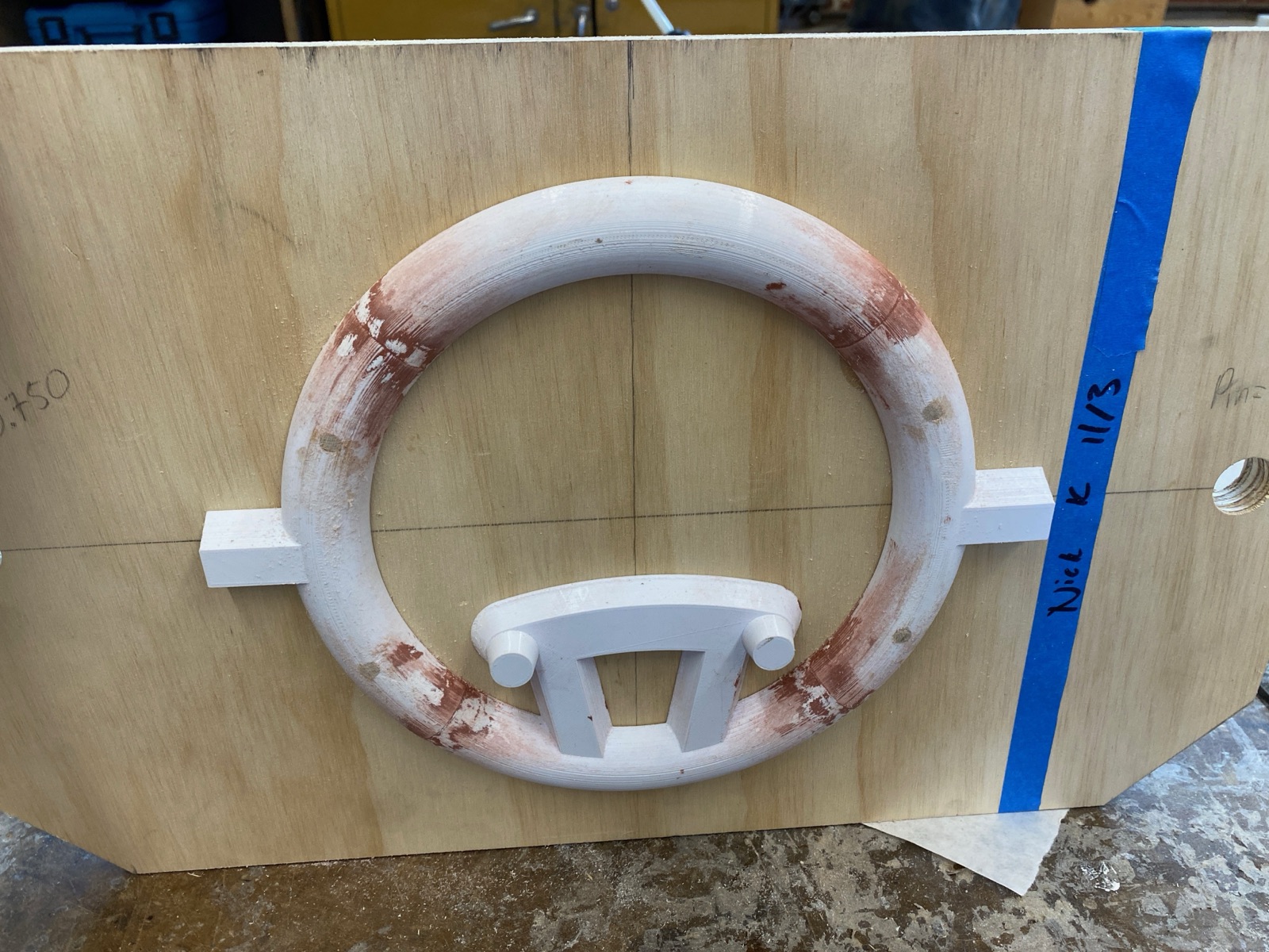
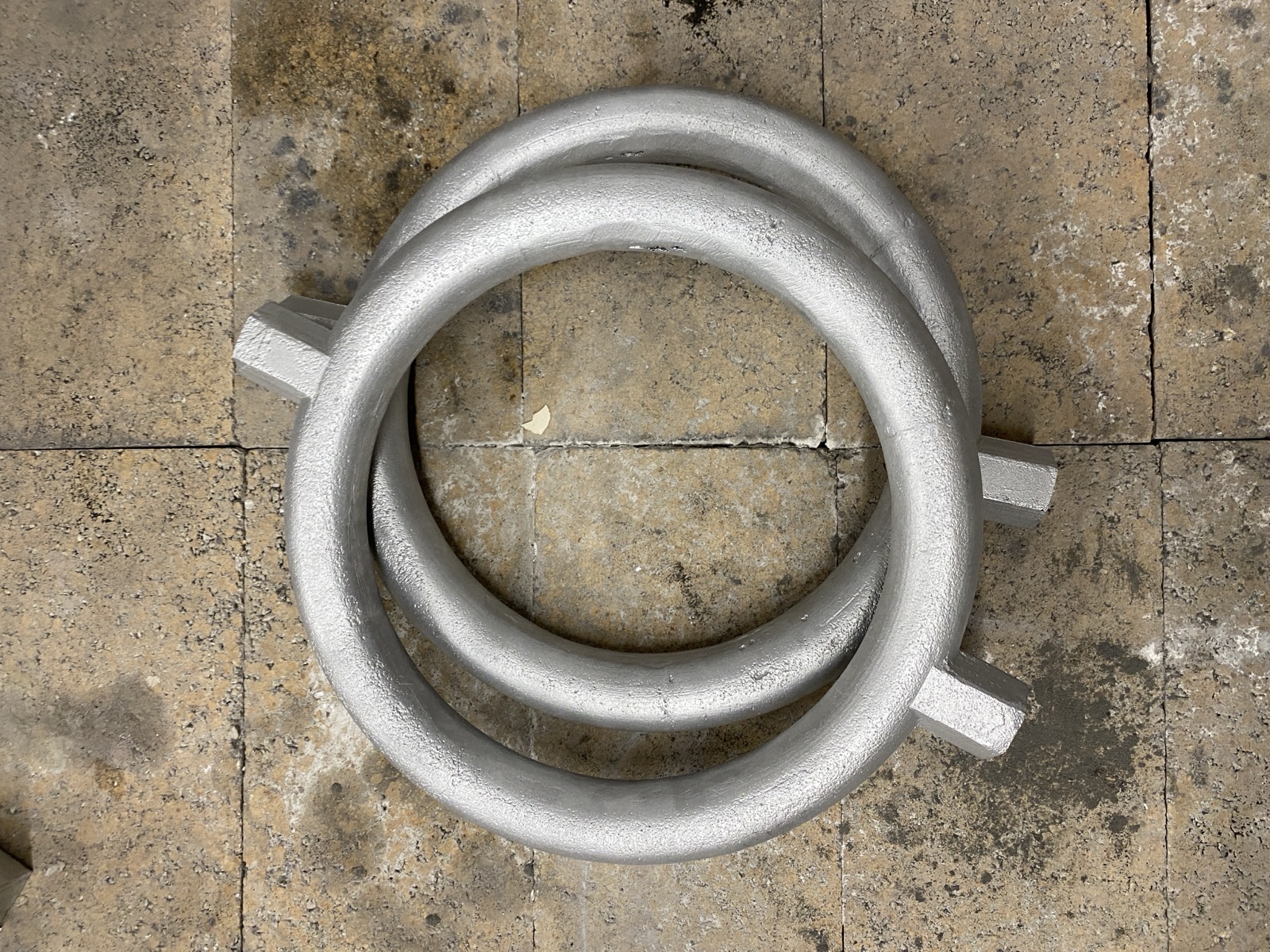
3. Sand Casting the Ring
With the hex design locked in, the ring needed to move from PLA to aluminum. Sand casting was the right process for two reasons: it handles the closed curved geometry of the ring without fixturing headaches, and the integrated hex pegs cast in one operation rather than being added later. The pattern was the PLA ring itself, split along a parting line.
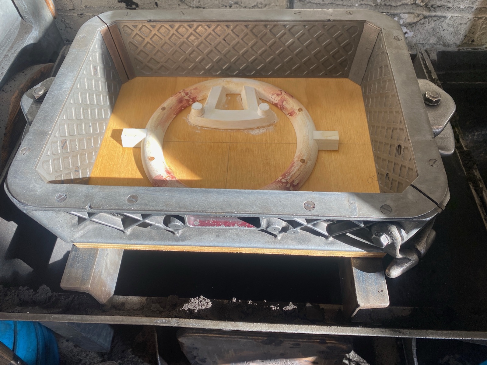
Pattern preparation
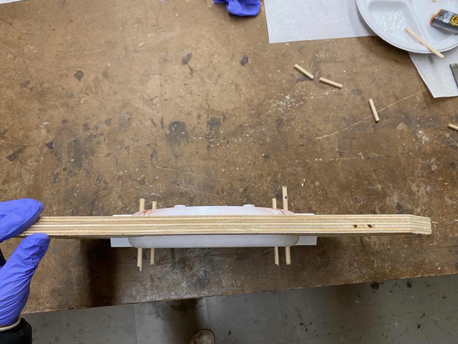
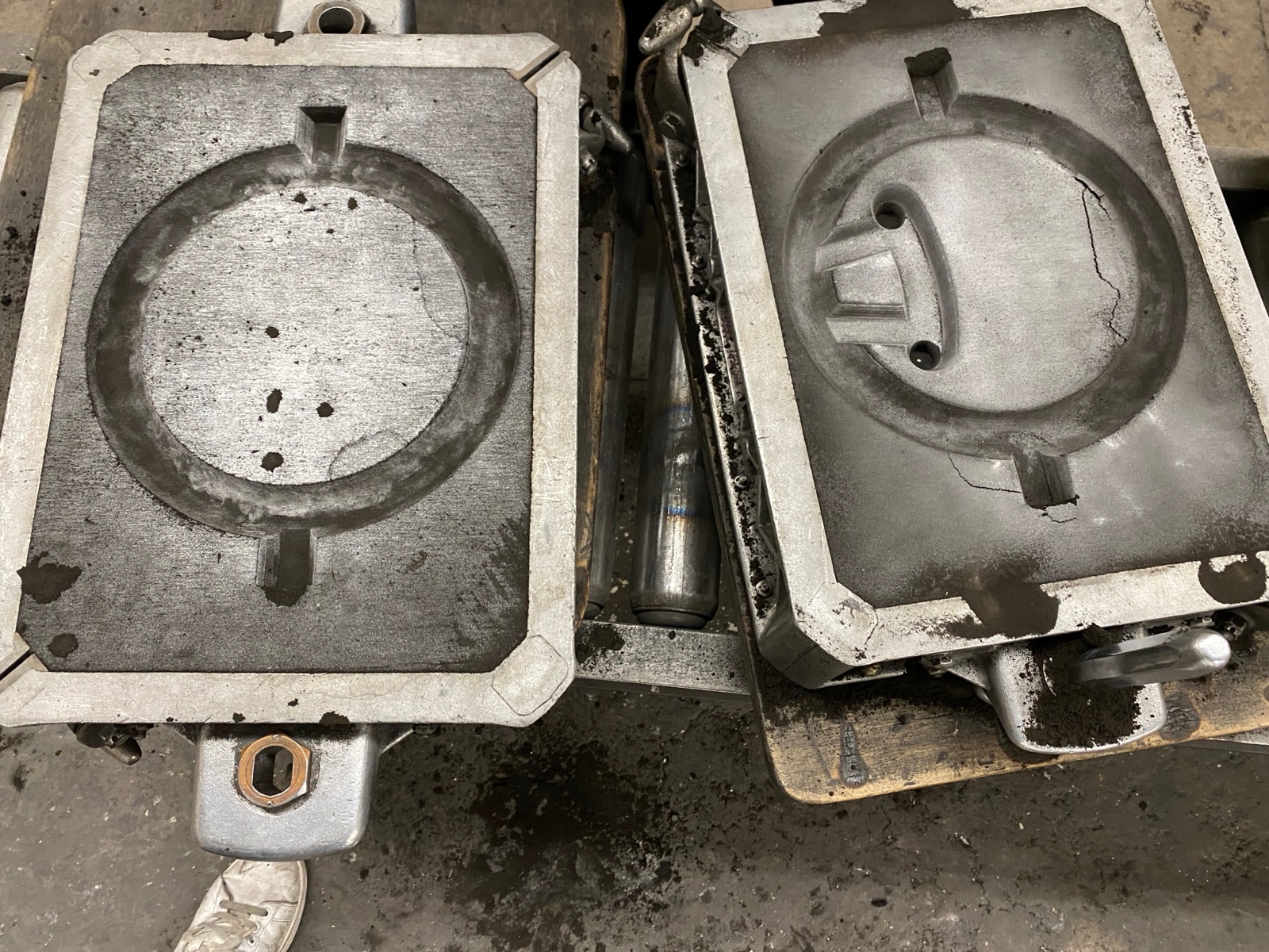
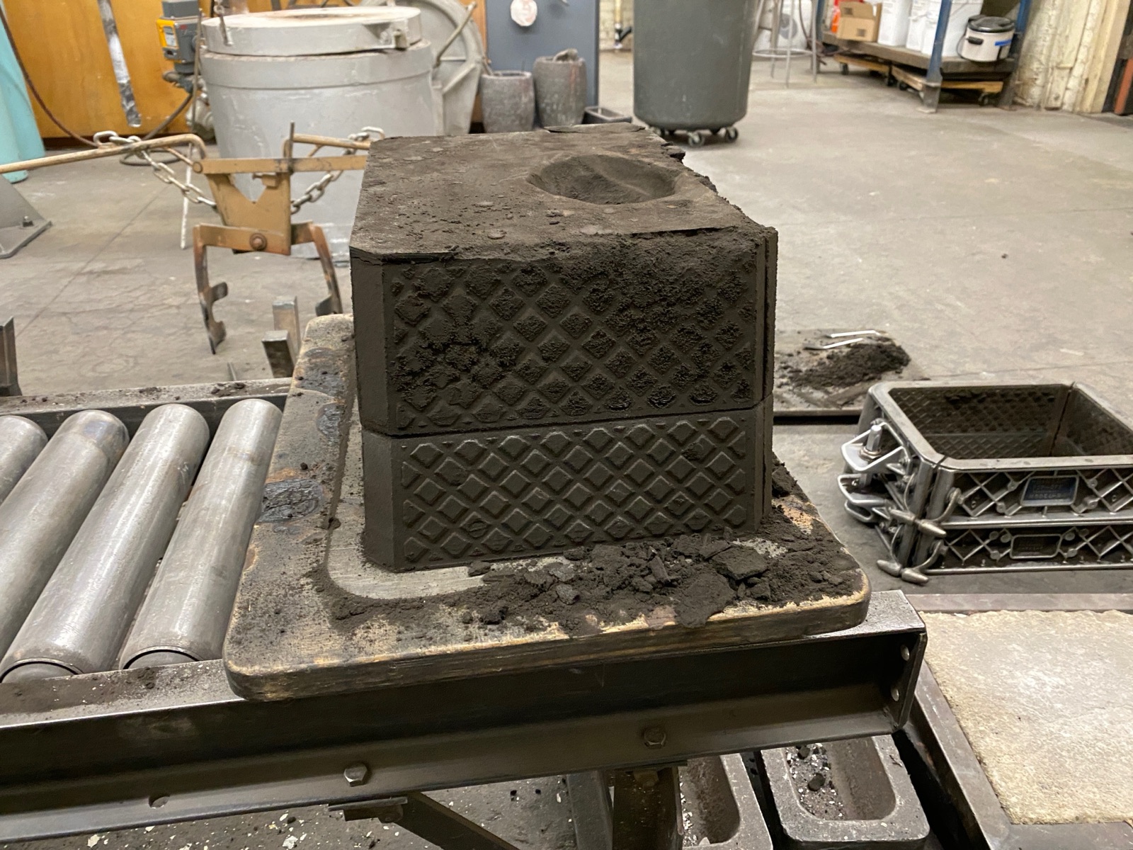
Mold making

Pour
Reveal
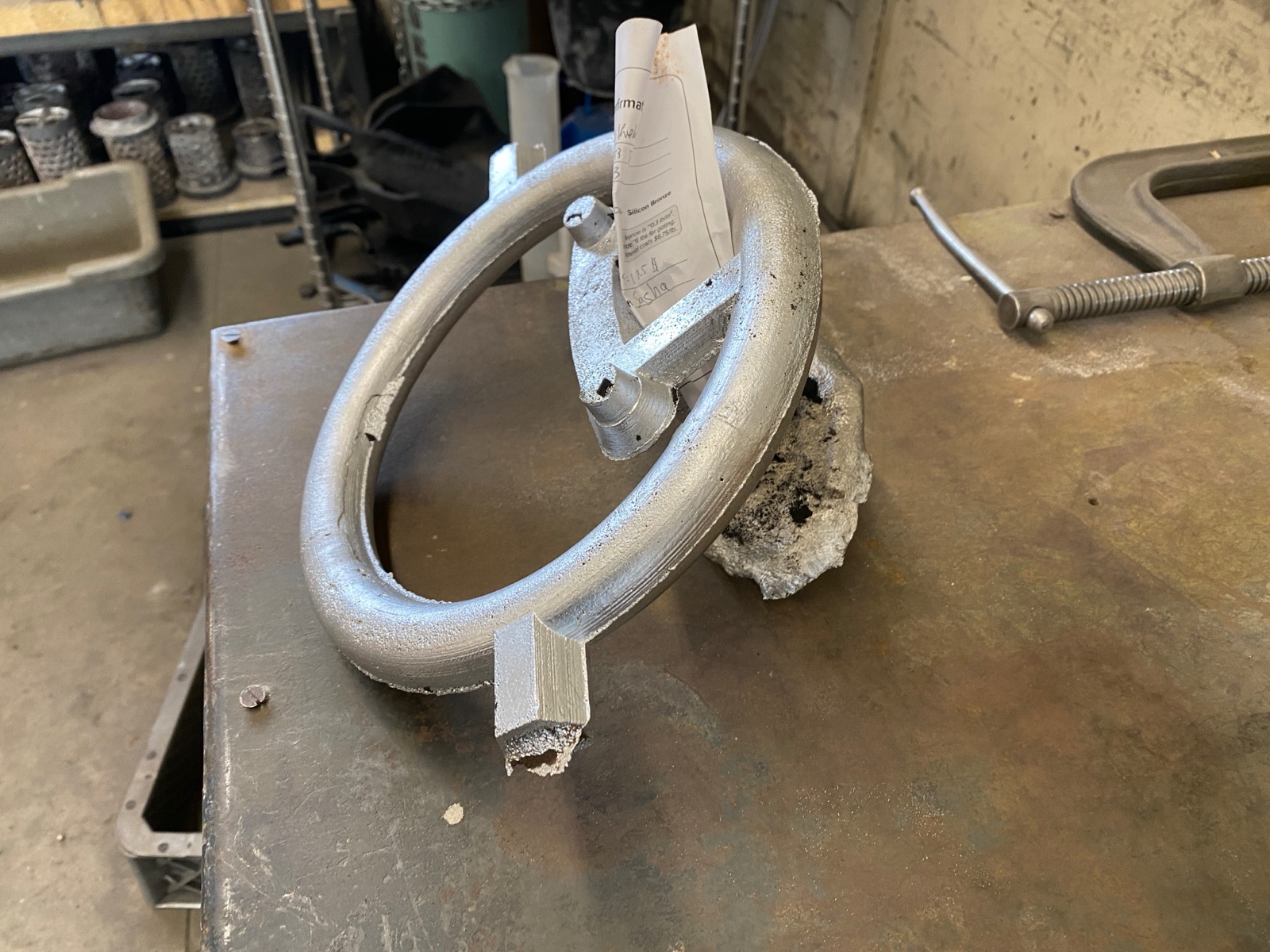
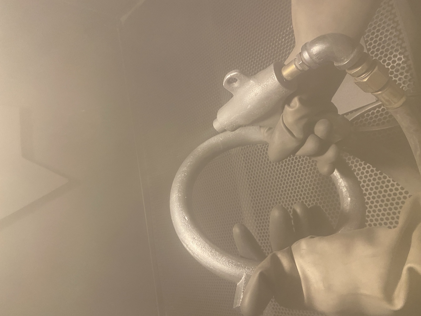
Cleanup
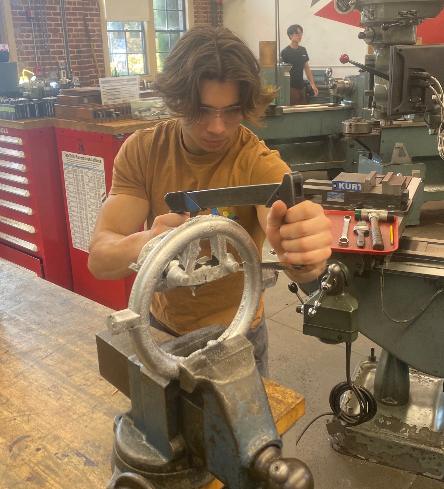
Surface finish
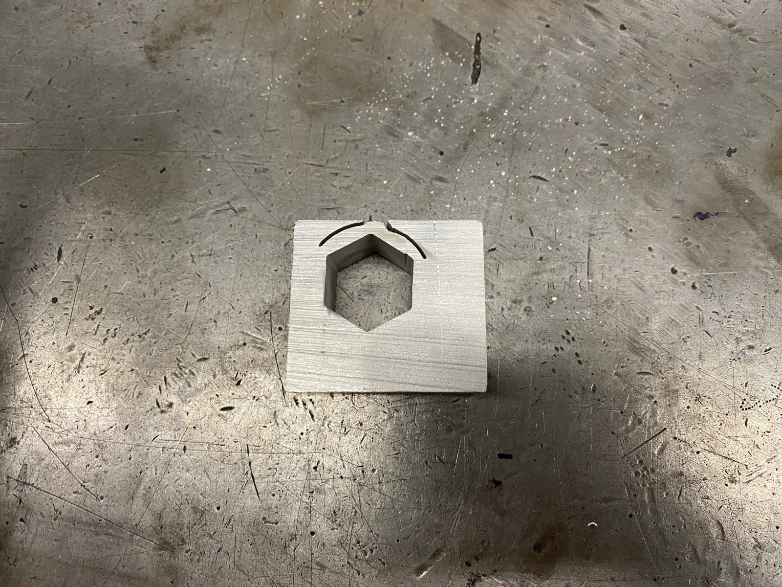
Tolerance check before committing
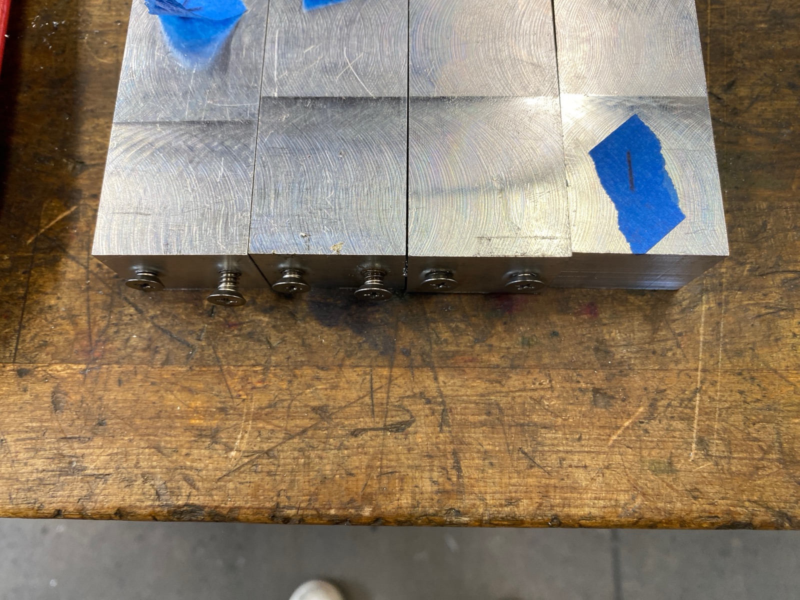
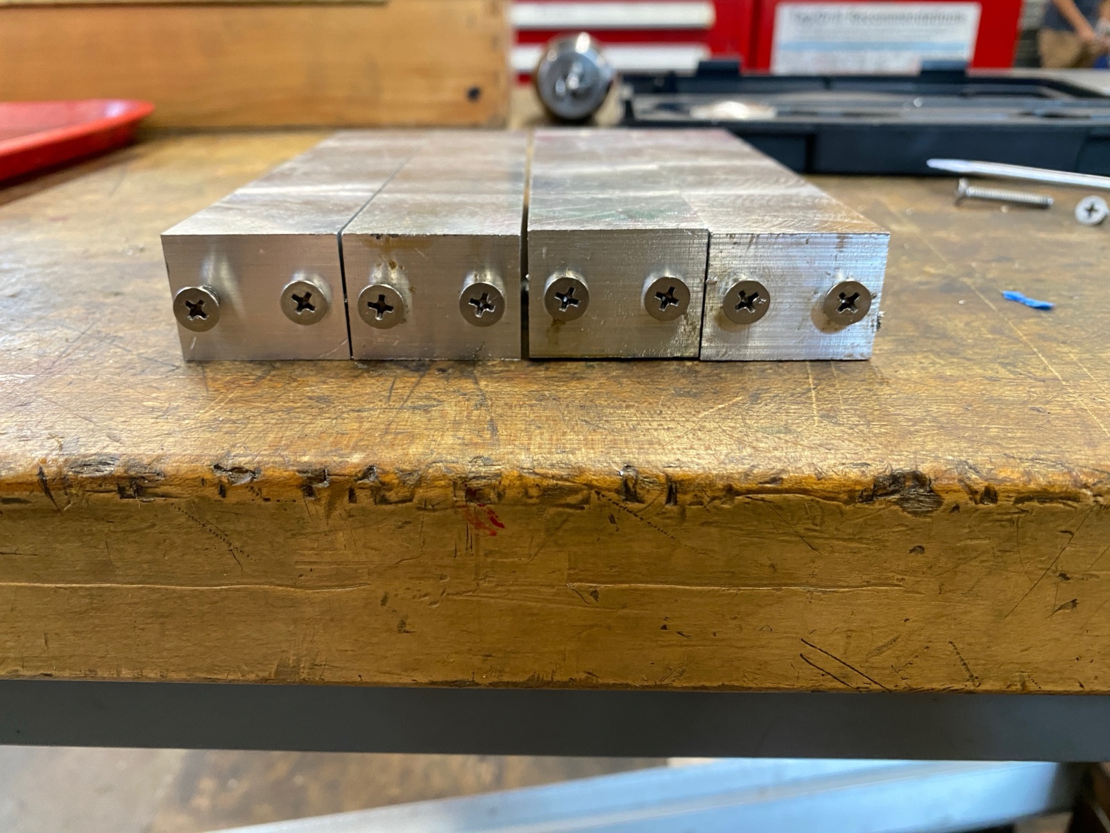
Before machining the actual legs, I cut hex test blocks at a few different sizes and fit them to a finished cast peg by hand. The goal was a peg that slides in firmly with finger pressure but doesn't rattle — a working friction fit. The test blocks let me dial in the hex hole dimension before cutting the real legs, where a single mistake would scrap a leg.
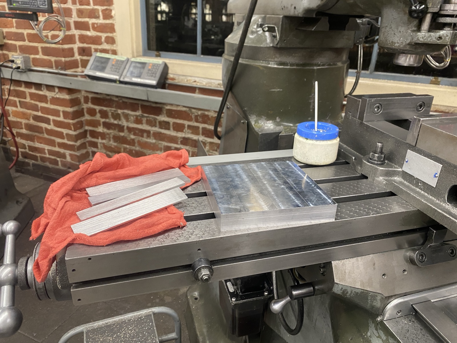
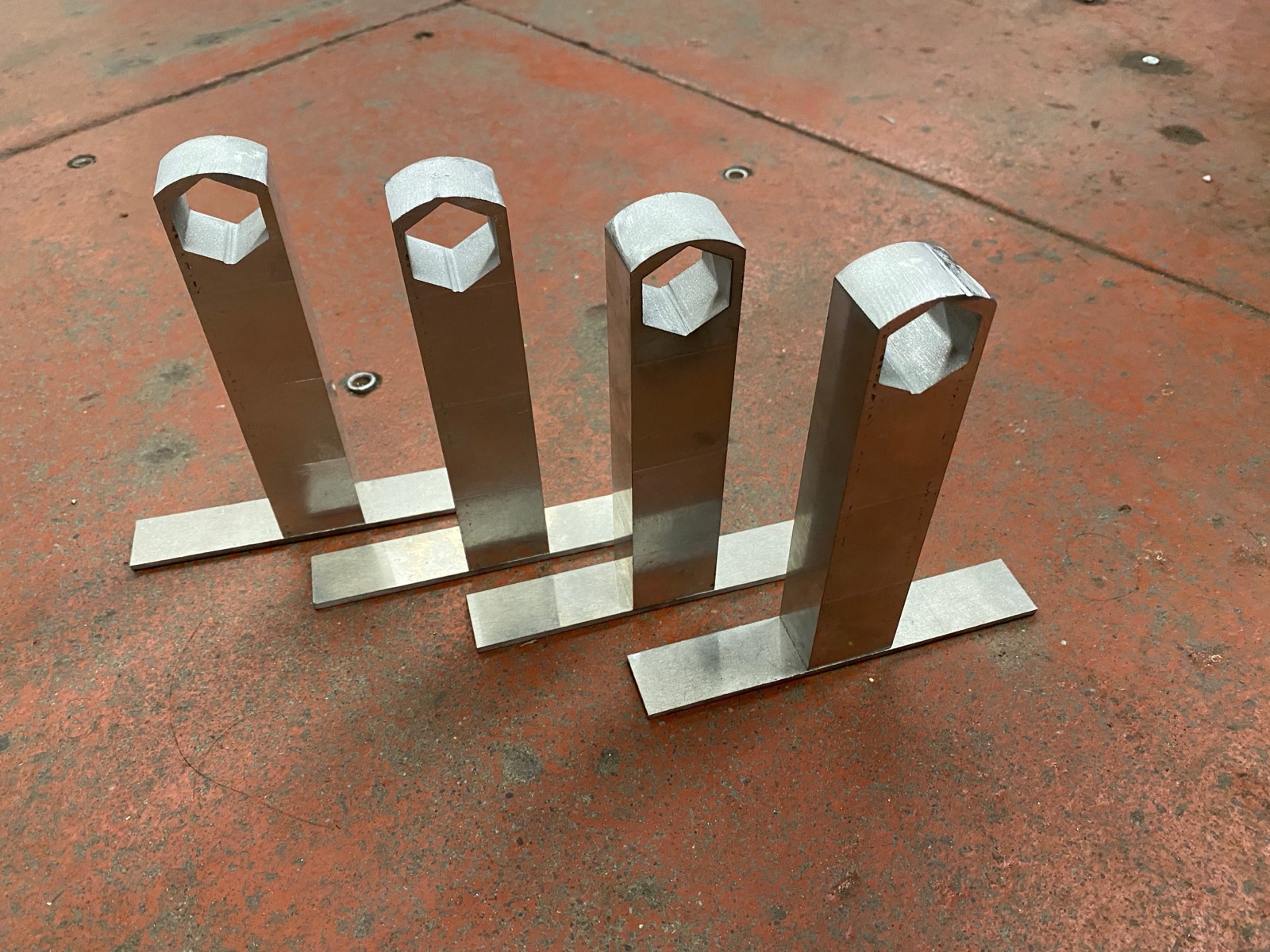
4. Legs (Mill + Water Jet)
The legs started as a single block of 6061-T6 aluminum. I faced and squared it on the manual mill, then cut it into four matched leg blanks. Each leg got two tapped holes for the baseplate screws, then went onto the water jet to cut the hex hole that mates with the cast peg. Cutting the hex on the water jet rather than the mill kept the hole geometry exactly matched to the test-block dimensions established in §3.
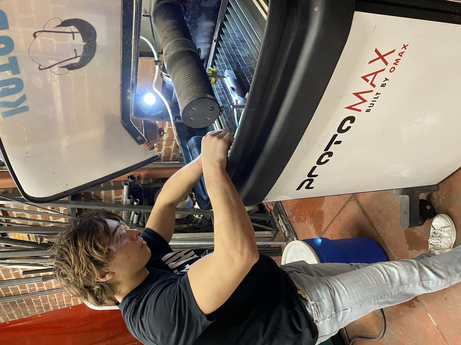
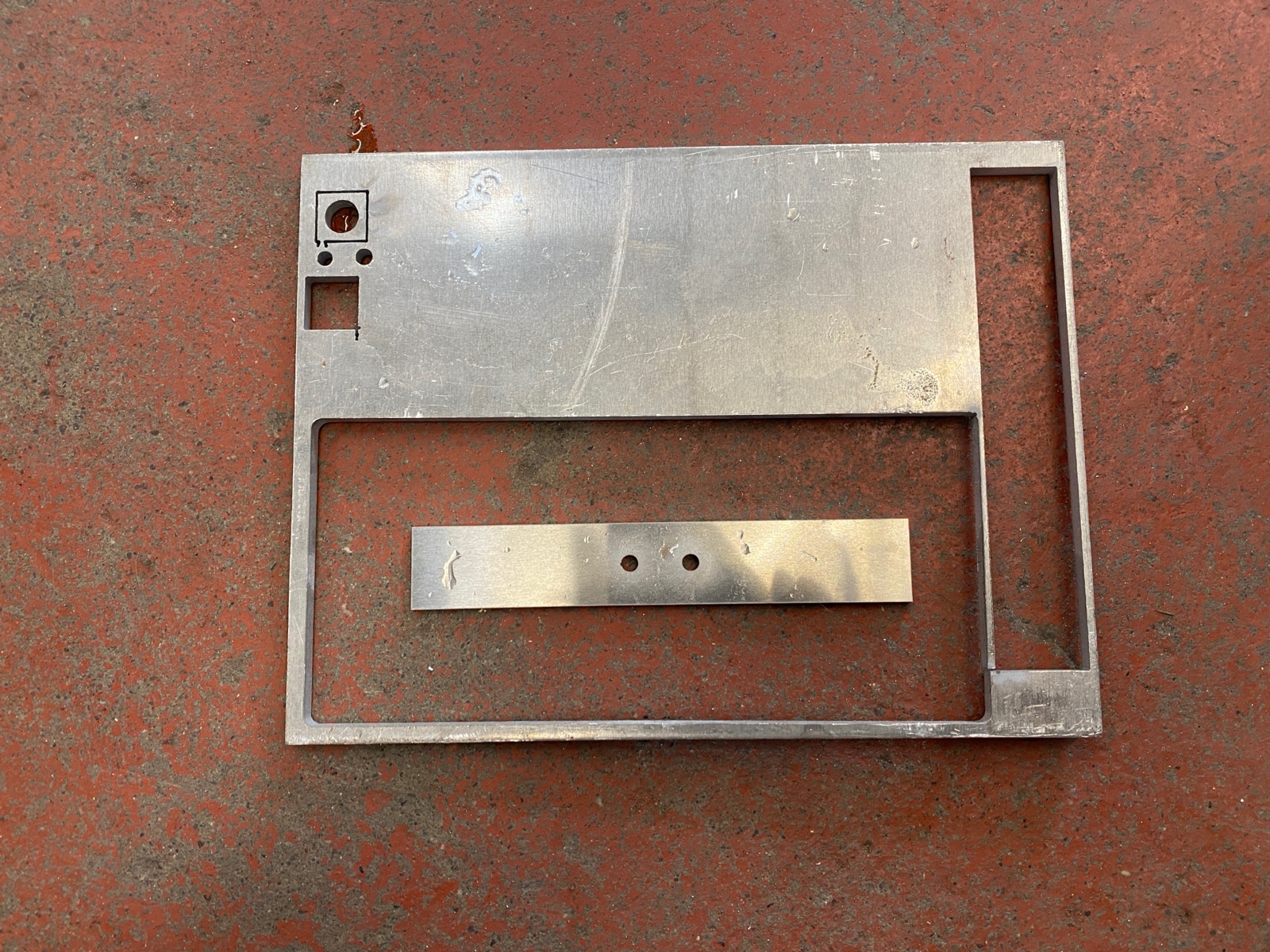
5. Baseplates
Baseplates were water-jet cut from aluminum sheet on the same OMAX machine, with the two through-holes for the leg screws cut in the same pass. Cutting the holes simultaneously with the outline guarantees they're concentric to the part — no secondary operation, no fixture error.
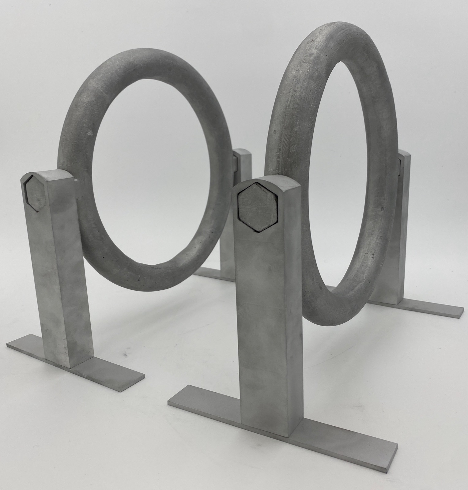
6. Final Assembly
With all four legs, two baseplates per side, and two cast rings ready, the final assembly is just press-fit and screw-down: hex pegs into the hex holes, baseplates screwed to the legs.
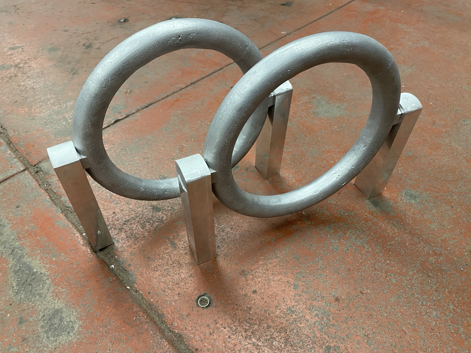
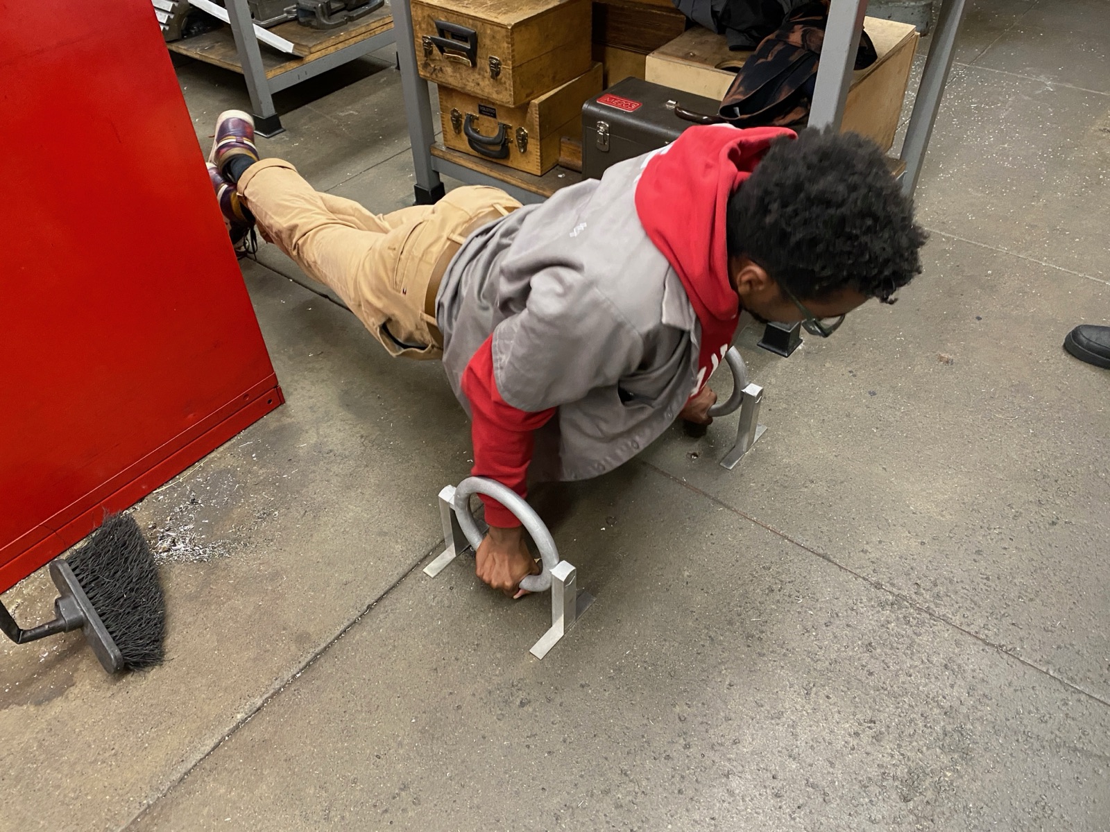
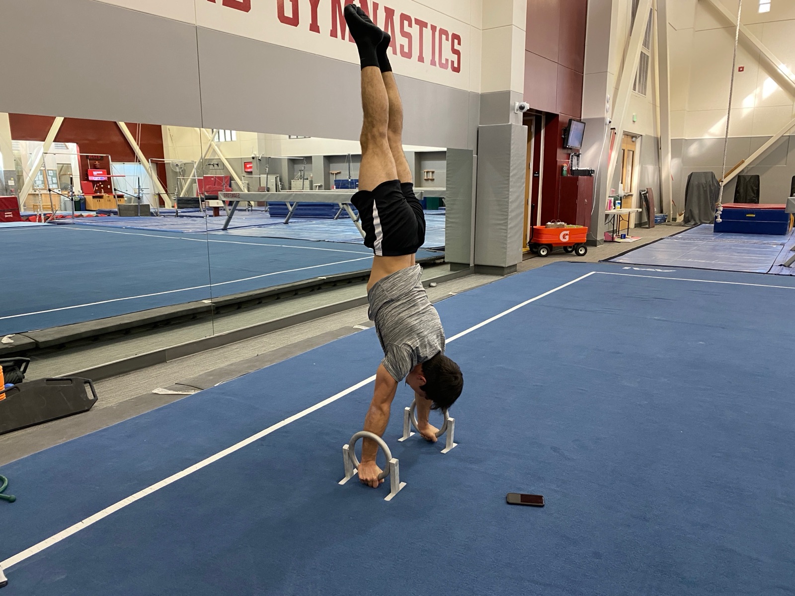
In the wild
Two early tests: