Ringallets — Force Analysis
Free-body diagrams, equilibrium, and the load each Ringallet can safely carry.
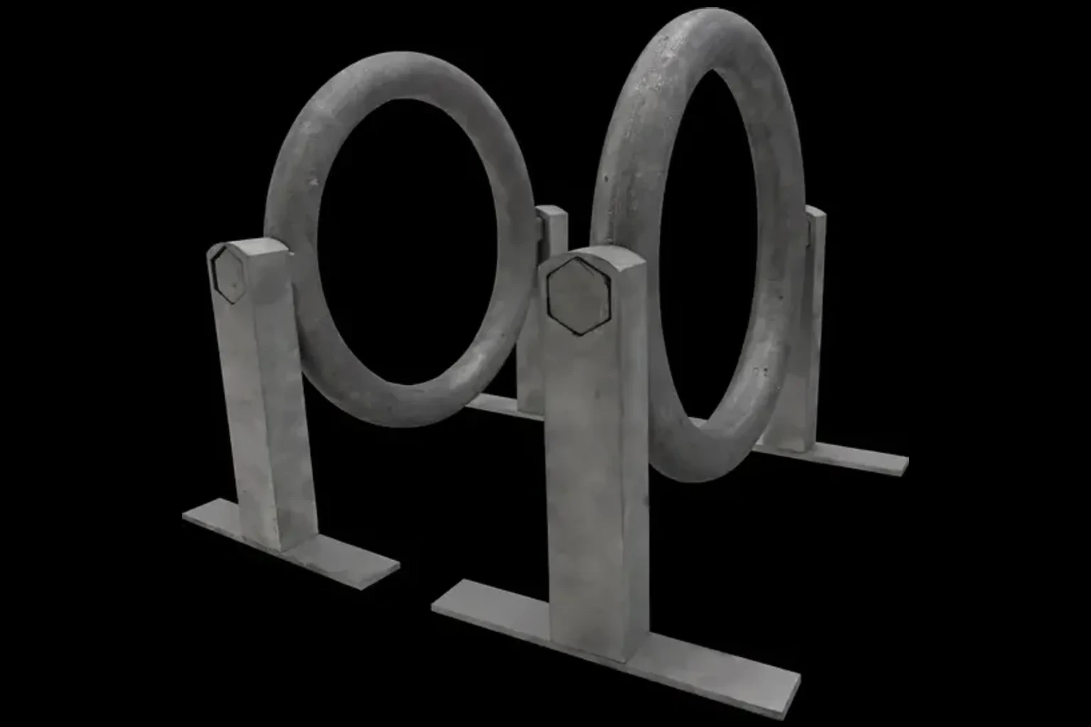
1. The System
Two milled 6061-T6 legs hold a sand-cast A356-T6 ring between them. The ring has two integrated hex pegs at its 3 and 9 o'clock points; each peg slides into a matching hex hole in a leg (hand-pressed friction fit, no glue or pin). Load P is a downward point force applied at the bottom of the ring during use.
The ring sits with intentional clearance between its bottom (6 o'clock) and the floor — that gap is what lets a hand wrap fully around the ring while gripping. It also rules out a bottom crossbar between the legs, since a crossbar would land exactly where the hand goes.
Ring (FIG-standard)
Inner Ø: 18 cm (7.09 in)
Grip Ø: 2.8 cm (1.10 in)
Centerline span between pegs: L = 20.8 cm (8.19 in)
Pegs (hex, integral to ring)
Across flats: 2.54 cm (1.000 in)
Across corners: 2.93 cm (1.155 in)
Length: 2.50 cm (0.986 in) — fully buried in leg
Legs (milled)
Cross-section: 3.50 × 2.54 cm (1.376 × 1.000 in)
Total height: 15.88 cm (6.251 in)
Peg center above floor: h = 14.35 cm (5.65 in)
Baseplate
15.24 × 2.54 × 0.318 cm (6 × 1 × 0.125 in), screwed to leg
Underside: bare aluminum
No rubber pad or floor anchor
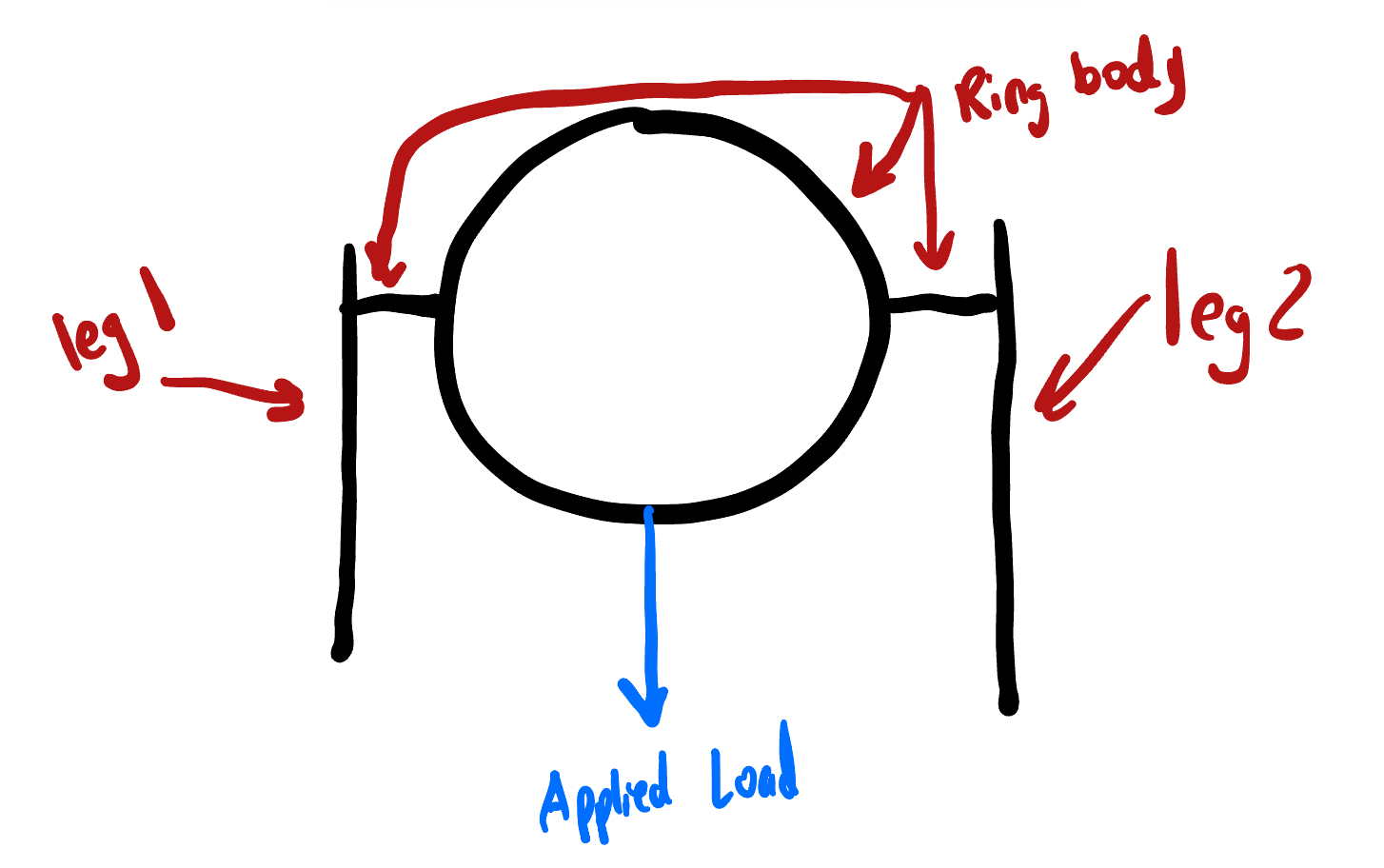
2. Reactions
The ring is loaded by P and supported through the two pegs. Isolating the ring gives the four peg reactions (Ax, Ay on the left, Bx, By on the right). Newton's third law transfers those reactions onto the legs, which are reacted at the floor by normal force N and friction F.
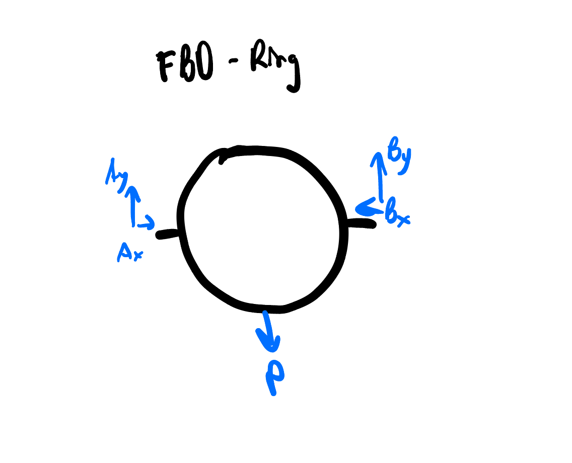
Vertical equilibrium of the ring
ΣFy = 0 → Ay + By − P = 0 → Ay = By = P / 2Horizontal equilibrium of the ring
ΣFx = 0 → Ax = Bx ≈ P / 2The closed ring is statically indeterminate in the horizontal direction. Treating the lower half as a shallow arch (span L = 2r, rise = r, point load at midspan) gives a first-order estimate of P/2 per side.
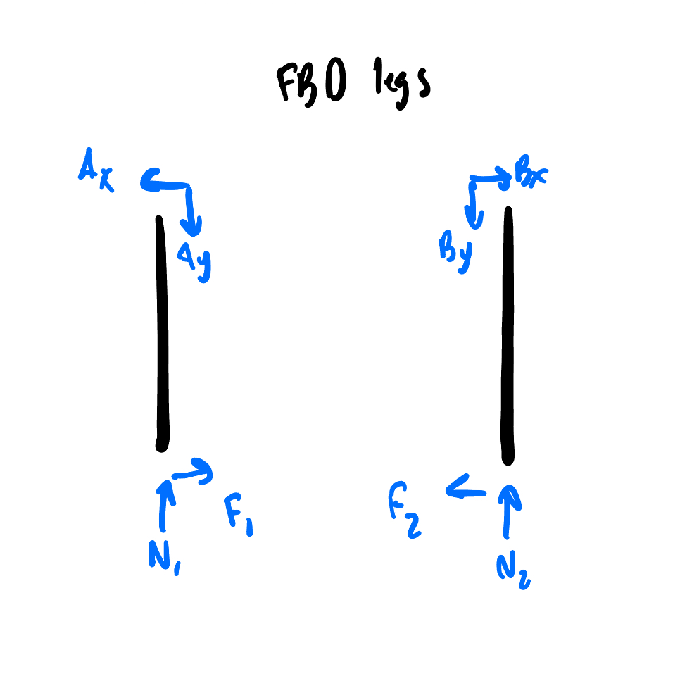
Leg reactions at the base
N₁ = N₂ = P / 2 F₁ = F₂ = P / 2Each foot carries half of P vertically and resists half of P horizontally. The required friction coefficient to prevent sliding is μ ≥ 1.0 — addressed in §5.
3. Failure-Mode Checks
Three modes can fail the assembly: ring bending, peg shear, and leg bending. Material yield strengths used: A356-T6 = 24 ksi, 6061-T6 = 40 ksi. Safety factor SF = 3 for safe working load.
3.1 Ring bending
Approximate the lower path of the ring as a simply-supported beam between the two pegs, with P applied at midspan.
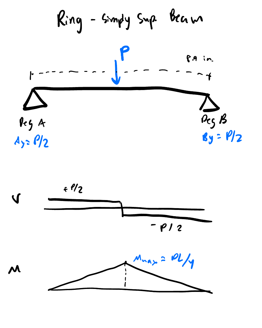
Solid round cross-section, d = 1.10 in (2.8 cm):
M_max = P · L / 4 = 2.05 P lb·in I = π d⁴ / 64 = 0.0725 in⁴ (3.02 cm⁴) c = d / 2 = 0.55 in (1.40 cm) σ_ring = M c / I = 15.6 P psiSolving σ_ring · SF = σyield for P:
P_safe = (24,000 / 3) / 15.6 ≈ 513 lb (233 kg)3.2 Peg shear
Each hex peg carries Ay = P/2 across an area of 0.866 in² (5.59 cm²) — regular hex with 1.0 in across flats. Shear stress is about 0.58 P psi — even at P = 1,000 lb that's 580 psi, far below A356 shear yield (~12 ksi). Not limiting.
3.3 Leg bending
The horizontal peg reaction Ax = P/2 creates a cantilever moment in the leg that peaks at the base.
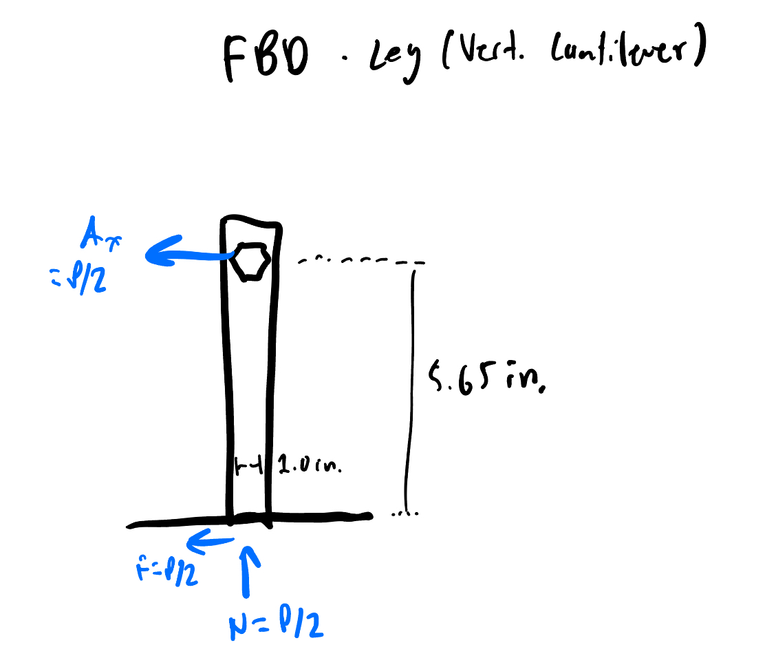
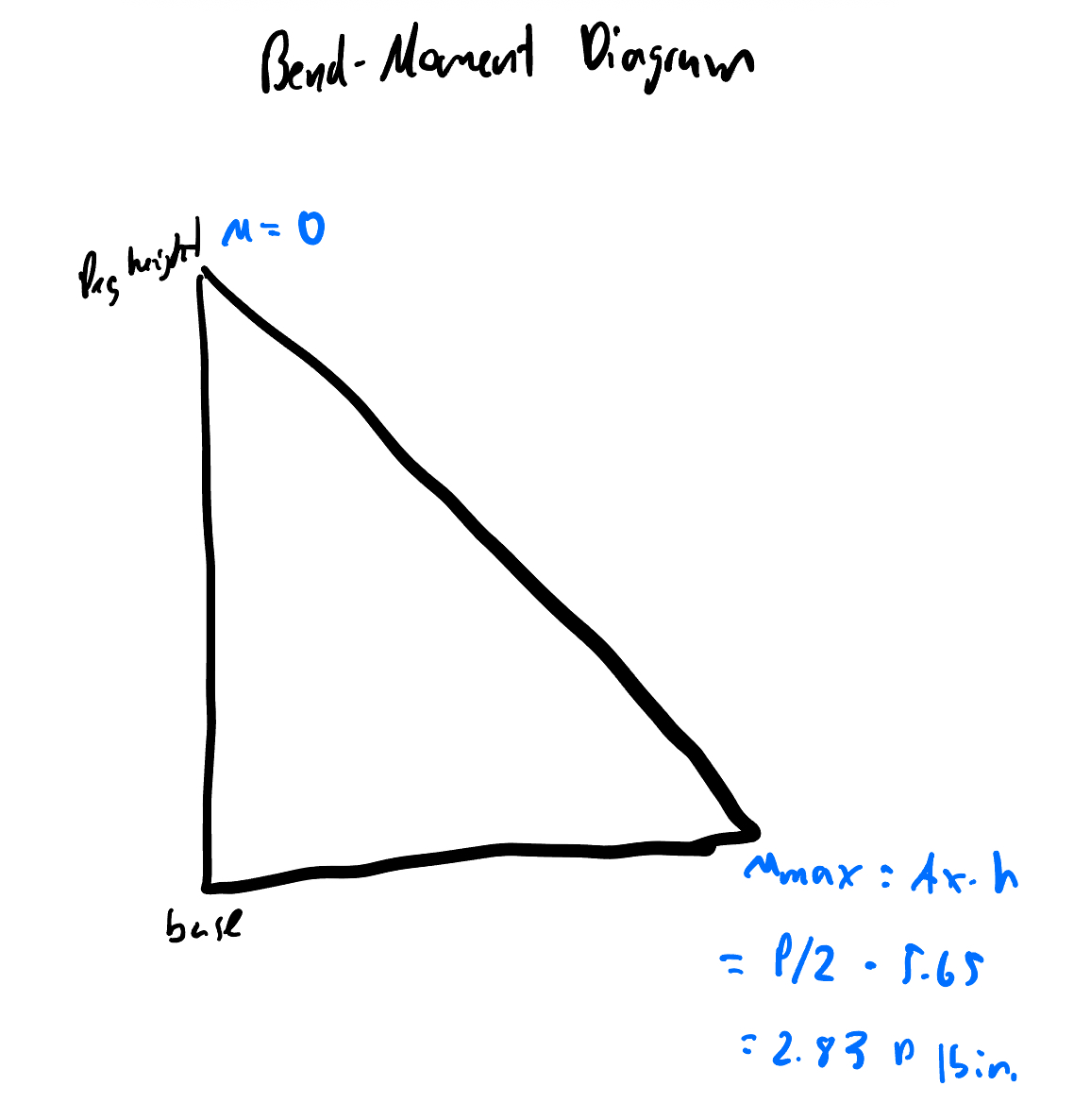
The leg bends about its weak axis — bending depth is the 1.0 in (2.54 cm) thin dimension. Section modulus:
M_max = Ax · h = (P/2)(5.65) = 2.83 P lb·in S = b h² / 6 = (1.376)(1.0)² / 6 = 0.229 in³ (3.75 cm³) σ_leg = M_max / S = 12.3 P psi P_safe = (40,000 / 3) / 12.3 ≈ 1,080 lb (490 kg)3.4 Friction-fit pullout
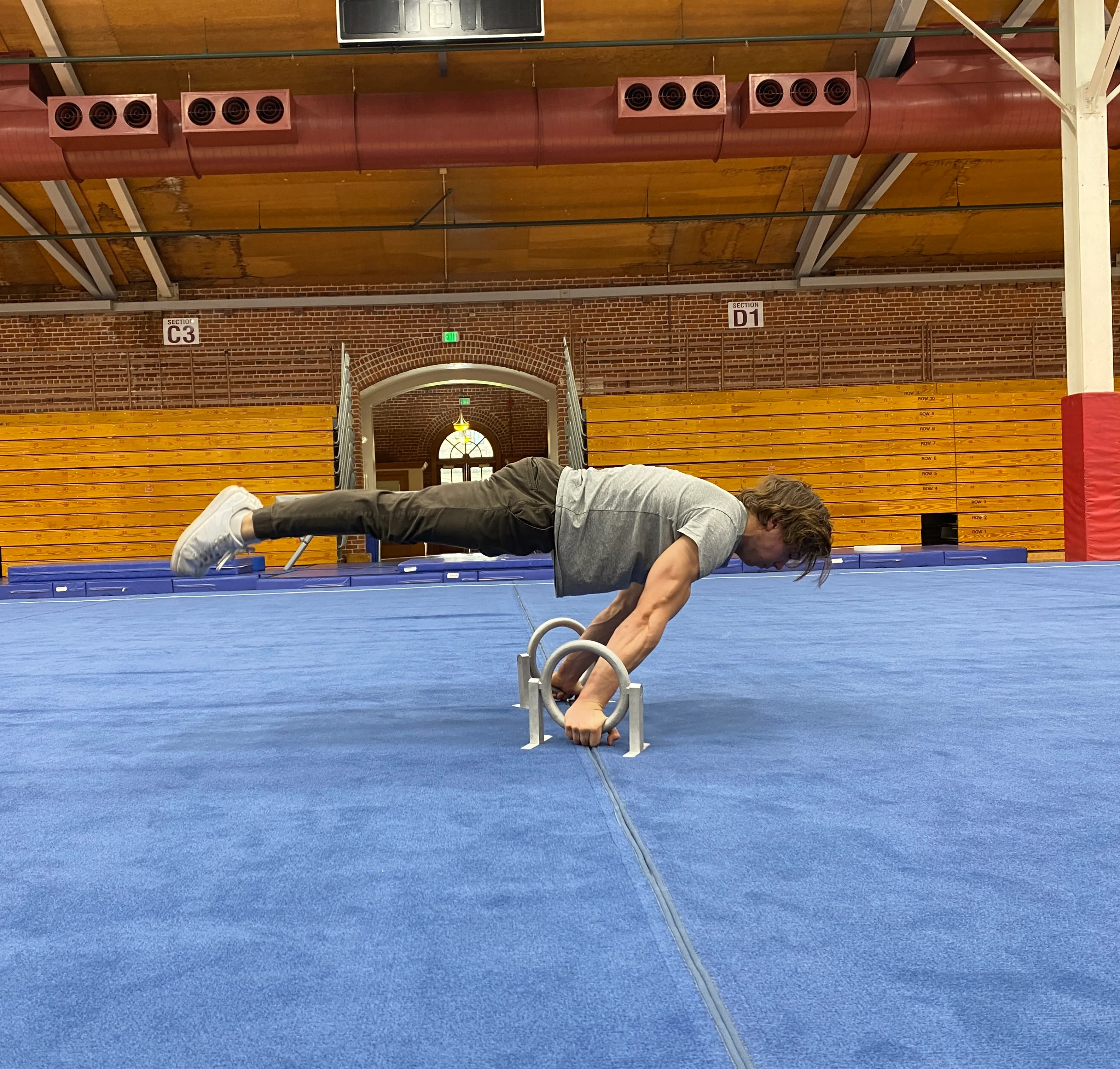
The peg is hand-pressed into the leg with no mechanical lock. Ax = P/2 tries to pull it out sideways. Pullout force was not measured analytically, but the demonstrated 160 lb (73 kg) planche bounds it from below: pullout per peg ≥ 80 lb (36 kg) under static use.
4. Result & Validation
The governing analytical mode is ring bending at ~513 lb per Ringallet. Leg bending and peg shear both have ~2× more headroom.
| Category | Load |
|---|---|
| Demonstrated prototype load (planche, static) | 160 lb (73 kg) |
| Ring-bending safe load (governs), per Ringallet | ~500 lb (227 kg) |
| Leg-bending safe load, per Ringallet | ~1,080 lb (490 kg) |
| Pair, two hands evenly loaded | ~1,000 lb (454 kg) |
| Margin over demonstrated load | ~3× |
One model note: the horizontal peg reaction Ax = P/2 comes from a 2-pin arch idealization. A closed ring is much stiffer than that model assumes, so the real horizontal thrust is meaningfully lower. Combined with the fact that calisthenics loads (handstand, support holds, dips) are nearly pure vertical, sliding has not been observed in testing.
5. Design Improvements
A bottom crossbar between the legs is the obvious structural fix — but it's incompatible with this design because the user's hand grips the ring at the 6 o'clock position, exactly where a crossbar would land. The two changes below do most of the work:
- Pin or bolt the peg through the leg. Eliminates the friction-fit pullout unknown and locks the joint against creep. Closes the only remaining un-quantified failure mode.
- Add rubber feet under the baseplates. Defensive measure for slick surfaces (polished tile, hardwood). Adds margin against any residual horizontal thrust.