WaterShield — Force Analysis
Why the original PLA fender cracked after a few rides, and how a two-body / steel-shaft redesign moved the failure mode out of the operating envelope.
1. The System
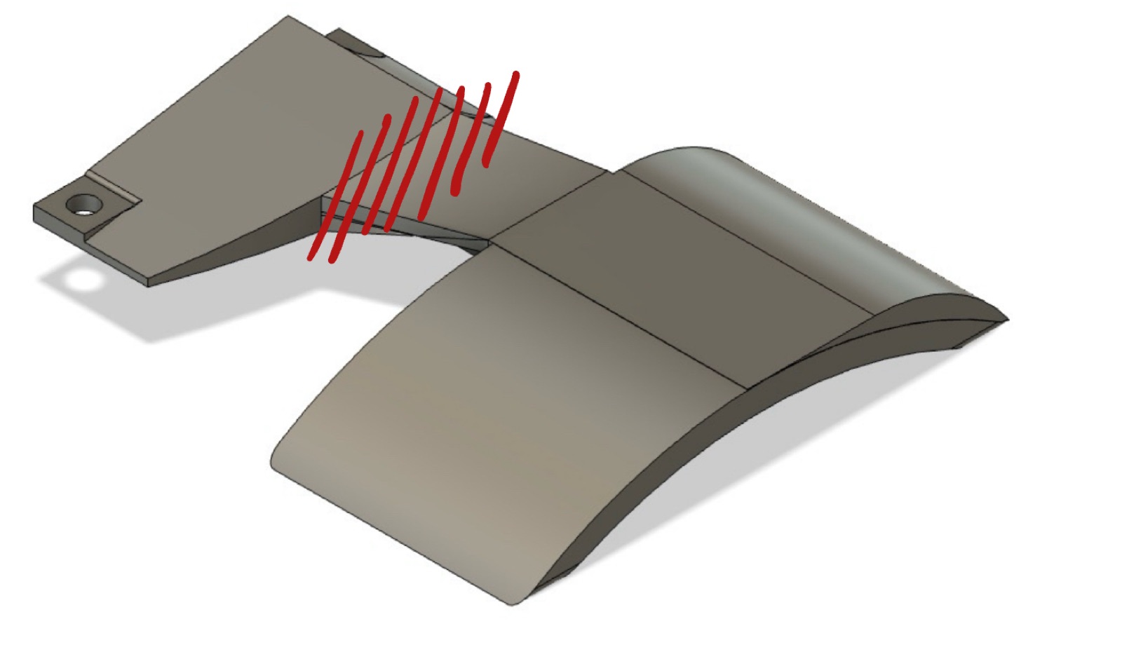
The WaterShield is a longboard wheel fender. It mounts to the deck via the existing truck-mount screws (no board modification) and cantilevers past the deck edge to cover the wheel from above. The arc is shaped to match the wheel profile — close enough to block the upward water spray, with clearance to never contact the wheel.
V1 is a single PLA body: the base plate flows continuously into the arc as one printed piece. After roughly three rides on rough pavement plus one large bump, it cracked at the geometric transition where the base plate meets the arc — exactly at the deck edge.
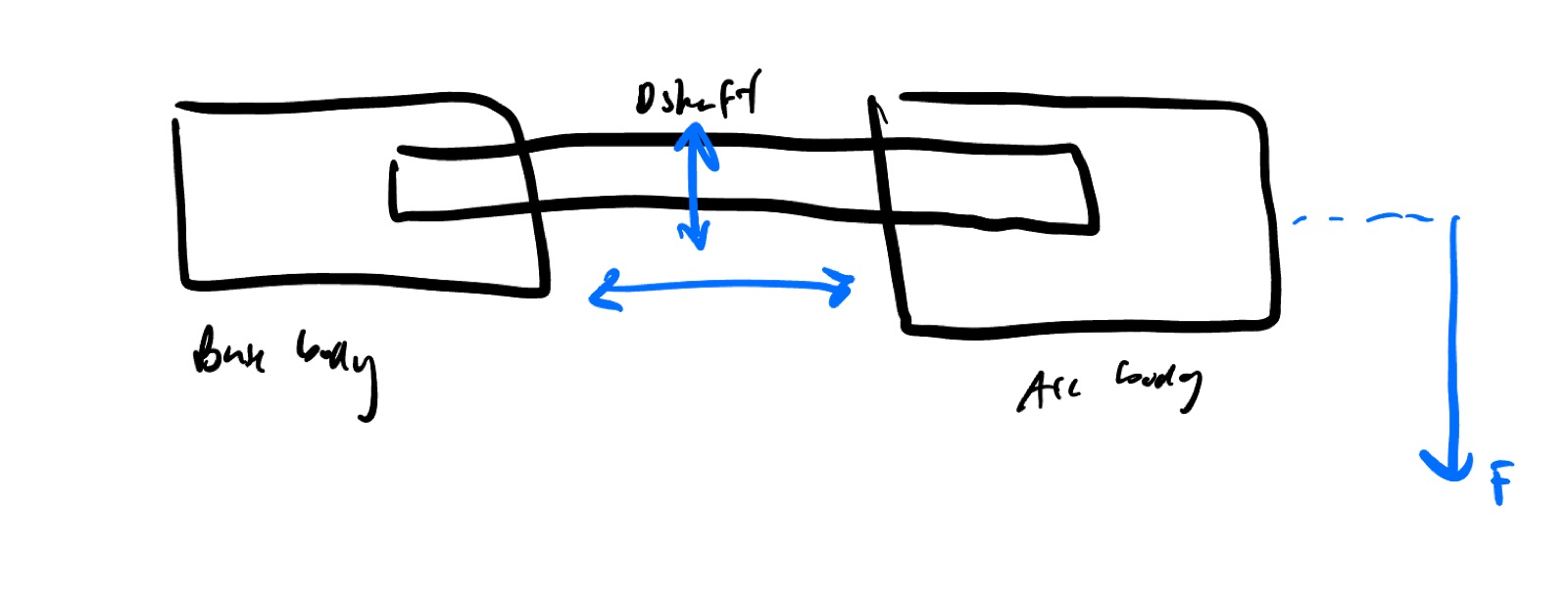
V2 splits the part into two PLA bodies (base + arc) joined by two 5 mm (0.197 in) steel D-shafts in tight friction-fit pockets. The D-shafts have a machined flat that bears against the pocket wall to prevent rotation. The joint sits inboard of the deck edge. External geometry, screws, and wheel coverage are unchanged — only the load path inside the part is different.
V1 — single body
Screw → tip: L_total = 4.937 in (12.54 cm)
Screw → deck edge / crack section: 1.375 in (3.49 cm)
Effective lever arm: L_eff = 3.562 in (9.05 cm)
Crack-section cross-section: b = 1.7 in × t = 0.3 in (4.32 × 0.76 cm)
V2 — two-body + D-shafts
Screw → tip: L_total = 5.000 in (12.70 cm)
Screw → joint plane: 0.938 in (2.38 cm)
Effective lever arm: L_eff = 4.062 in (10.32 cm)
Arc-body section just outboard of joint: b = 4.8 in × t = 0.442 in (12.19 × 1.12 cm)
D-shafts (V2 only)
Diameter: 5 mm (0.197 in), steel
Spacing (centerline): 1.193 in (3.03 cm), side-by-side along the board
Insertion depth: 1.0 in (2.54 cm) into each body
Pocket: ~0.03 in (0.76 mm) diametral oversize for kerf compensation
Mounting (both versions)
Two truck-mount screws, stacked along the board's length
Center-to-center spacing: 2.5 in (6.35 cm)
Material: PLA, Bambu Lab, vertical print orientation
Loading: F = vertical force at the arc tip from road bumps and water spray
2. Reactions
Both versions are cantilever beams. The screw pair forms the fixed support; F is applied at the tip of the arc. The relevant internal loads at any cross-section a distance x from the tip are:
V1 fails where the cross-section is weakest, not where M is largest in absolute terms — the two happen to coincide at the body→arc transition. V2 moves the support inboard (the joint takes over from the screw pair as the practical fixity point for the arc) and adds a much stronger PLA section outboard of it.
3. Failure-Mode Checks
Three modes can fail the assembly: V1 PLA bending at the body→arc transition, V2 PLA bending outboard of the joint, and V2 joint capacity. Material strength: PLA in vertical-print orientation puts the layer lines perpendicular to the bending stress (the worst orientation). Effective layer-perpendicular bending strength is taken at σ_y = 5,000 psi — conservative against the 7–9 ksi isotropic value, accounting for layer adhesion. Safety factor SF = 3.
3.1 V1 — PLA bending at the body→arc transition
Rectangular section under simple bending. With b = 1.7 in, t = 0.3 in, L_eff = 3.562 in:
F · L_eff at the crack section.Solving σ · SF = σ_y for F:
3.2 V2 — PLA bending in the arc body, outboard of the joint
Same approach, applied to the arc body at the section just outboard of the joint plane. With b = 4.8 in, t = 0.442 in, L_eff = 4.062 in:
The V2 arc body is wider and thicker than V1's crack section, so it carries about 5.4× more bending stress per unit of tip force. That single change accounts for the bulk of V2's strength gain.
3.3 V2 — joint capacity
The two D-shafts sit side-by-side along the board, both at the same height (forced by a 0.6 in tall base body and 1.193 in shaft spacing — they cannot fit stacked vertically). They therefore do not form a vertical force couple resisting the bending moment directly. The joint reacts the moment through three mechanisms working together:
F · L_eff, reacted by joint-face compression + pin shear + pocket friction.- PLA-on-PLA compression at the bottom edge of the joint face — the two bodies push against each other where bending closes the joint.
- Pin shear — both pins together carry the transverse shear
F; each pin seesF/2across an area ofπ d²/4 ≈ 0.030 in². At a steel shear yield of ~21 ksi (mild steel, SF = 3), each pin can carry ~210 lbf — the joint is nowhere near pin-shear-limited. - Pocket friction — when bending tries to open the top of the joint, friction along the 1 in shaft insertion in each body resists axial pullout.
The combined joint capacity is dominated by PLA-on-PLA contact and friction-fit behavior, which don't have clean closed-form solutions in simple statics. The honest answer here is empirical: V2 has been ridden ~15 times with no detectable joint slop, deformation, or shaft motion, so the joint has not been the limit in practice. The page-side bound is the §3.2 PLA bending number.
4. Result & Validation
The governing analytical mode for V1 is PLA bending at the body→arc transition at ~11.9 lbf. The governing analytical mode for V2 is PLA bending in the arc body outboard of the joint at ~64 lbf — about 5.4× stronger. Joint capacity in V2 is empirically validated; pin shear has ~10× more headroom than the PLA bending check.
| Version | Governing mode | Safe load at tip |
|---|---|---|
| V1 (single PLA body) | PLA bending at body→arc transition | ~12 lbf (5.4 kg) |
| V2 (two-body + 2× steel D-shaft) | PLA bending in arc body, outboard of joint | ~64 lbf (29 kg) |
| V2 — pin shear (sanity check) | Steel D-shaft cross-section | ~420 lbf (190 kg) total |
| V2 — joint contact + friction | not analytically closed | empirically validated, no slop after ~15 rides |
Fatigue life — how many rides before V2 fails?
V1 failed in roughly 3 rides at the operational riding load. V2's PLA weak section sees σ_V2 / σ_V1 = 26.0 / 139.7 ≈ 0.186 — about 1/5.4 of V1's stress at the same tip force. Using Basquin's law for plastic fatigue with exponent k ≈ 8 (typical for PLA):
So at the same operational load, V2's fatigue life is on the order of 700,000× longer than V1's. Translated to ride count, that's well into the millions. Fatigue is no longer the design driver — V2's realistic failure mode is a single catastrophic impact (curb strike, drop, wheel-against-arc contact in a hard turn), not cyclic vibration.
One model note: the operational load itself (the actual F at the tip during a ride) was not measured directly — it's bounded by V1's failure case (around 8–12 lbf at peak, since V1 was cracking near its analytical limit) and by V2's continued survival. Both versions experience the same external load; only the load path through the part changed.
5. Design Improvements
V2 already moves the failure mode out of the fatigue regime. The remaining improvements are about hardening V2 against the impact case and tightening the analysis on the joint:
- Stack the D-shafts vertically. Currently they sit side-by-side at the same height because the base body is only 0.6 in tall. Increasing the body height to ~1.7 in would let the shafts be vertically separated, forming a proper moment couple — the joint would then resist bending directly through pin tension/compression rather than relying on PLA-on-PLA contact + friction. That's the single biggest analytical win available.
- Add a fillet at the body→arc transition (V1-style geometry, if reverting). Even if the part stays a single piece, removing the sharp geometric step would significantly improve fatigue life by reducing the stress concentration at the crack section.
- Print the arc body in the bending-favorable orientation. Vertical print puts the layer lines perpendicular to the bending stress. Printing flat (or at an angle that aligns layers with the principal stress direction) would close the gap between layer-perpendicular and isotropic PLA strength.
- Add a mechanical retention feature to the shafts. The current friction-fit relies on uniform print-kerf compensation. A small pin or set screw across each shaft would lock the joint against creep over the long term.