WaterShield — Process

From the CAD model through three printed iterations of V1, the on-board failure, and the two-body friction-fit redesign that now carries every ride.

PLA, vertical print Bambu Lab 5 mm steel D-shafts Truck-mount fixity

1. CAD Models

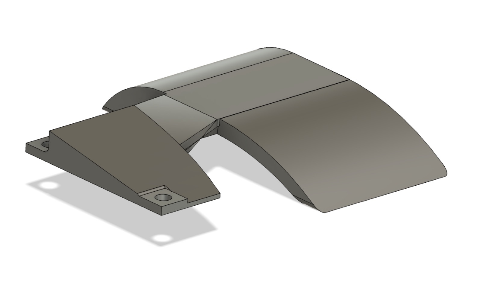
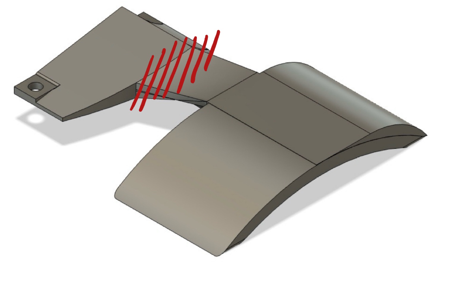
Both versions share the same external geometry: a base plate sized to the truck-mount screws and an arc shaped to wrap the wheel from above with clearance. The structural change between V1 and V2 lives entirely on the interior — V1 is one continuous PLA body, V2 splits into two bodies joined by two steel D-shafts.

V1 CAD render — single PLA body with the base plate flowing continuously into the arc.
V1 — single PLA body, continuous base→arc geometry.
V2 CAD render — two-body design with separate base plate and arc body, joined by two D-shafts.
V2 — two PLA bodies, joined by two 5 mm steel D-shafts (not visible in the render).

2. V1 — Print, Mount, Failure

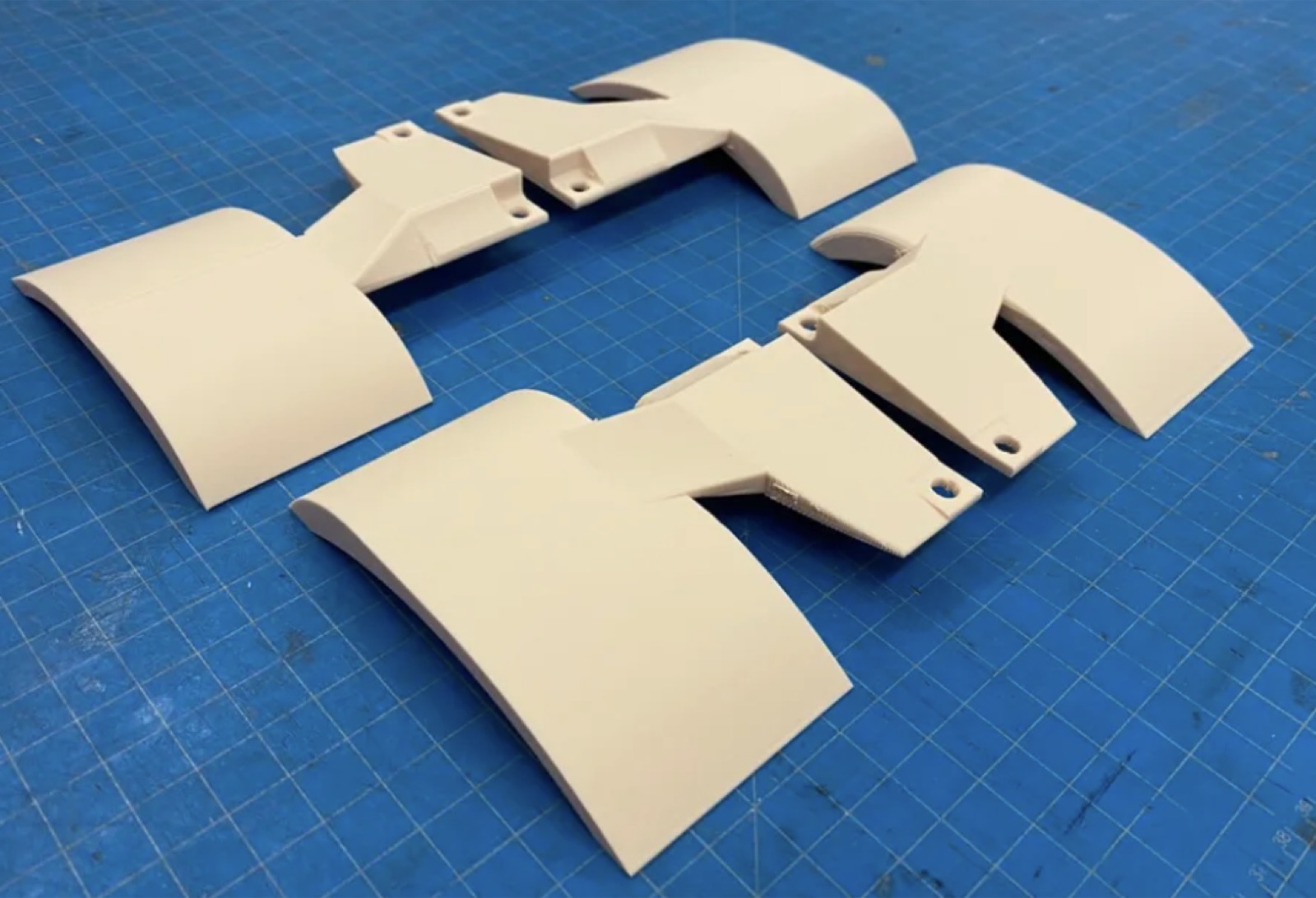
V1 went through three printed iterations on the Bambu Lab. The earliest prints used a thicker, "doorstop"-like base plate that worked structurally but looked oversized. Subsequent iterations slimmed the geometry down to the final form factor, then a painted refinement pass for the field test.

Multiple V1 PLA print iterations laid out on a blue cutting mat, showing the base plate and arc geometry refining across versions.
Three V1 print iterations side by side — early bulky base plate (top) trimmed down to the final form (bottom).
V1 final refined version, primed and painted dark gray, sitting on a white surface.
The refined V1 — primed and painted before the on-board test.
V1 CAD render with red hatching marking the failure location at the body-to-arc geometric transition.
Failure location annotated on the CAD: the part snapped at the body→arc transition where the cross-section steps and the print layer lines run perpendicular to the bending stress.
V1 WaterShield mounted on the longboard during a test ride, white fenders visible covering the wheels.
V1 mounted on the longboard. Survived ~3 rides before cracking at the location shown above; see the force-analysis writeup for the full failure breakdown.

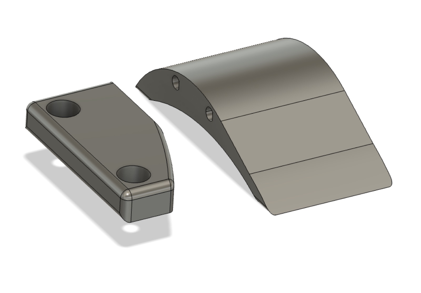
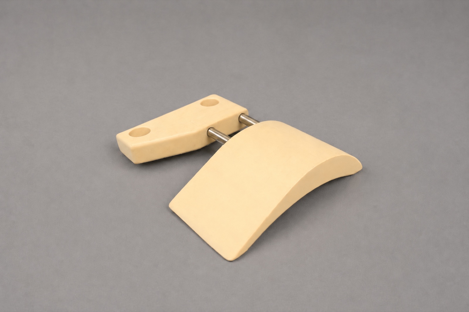
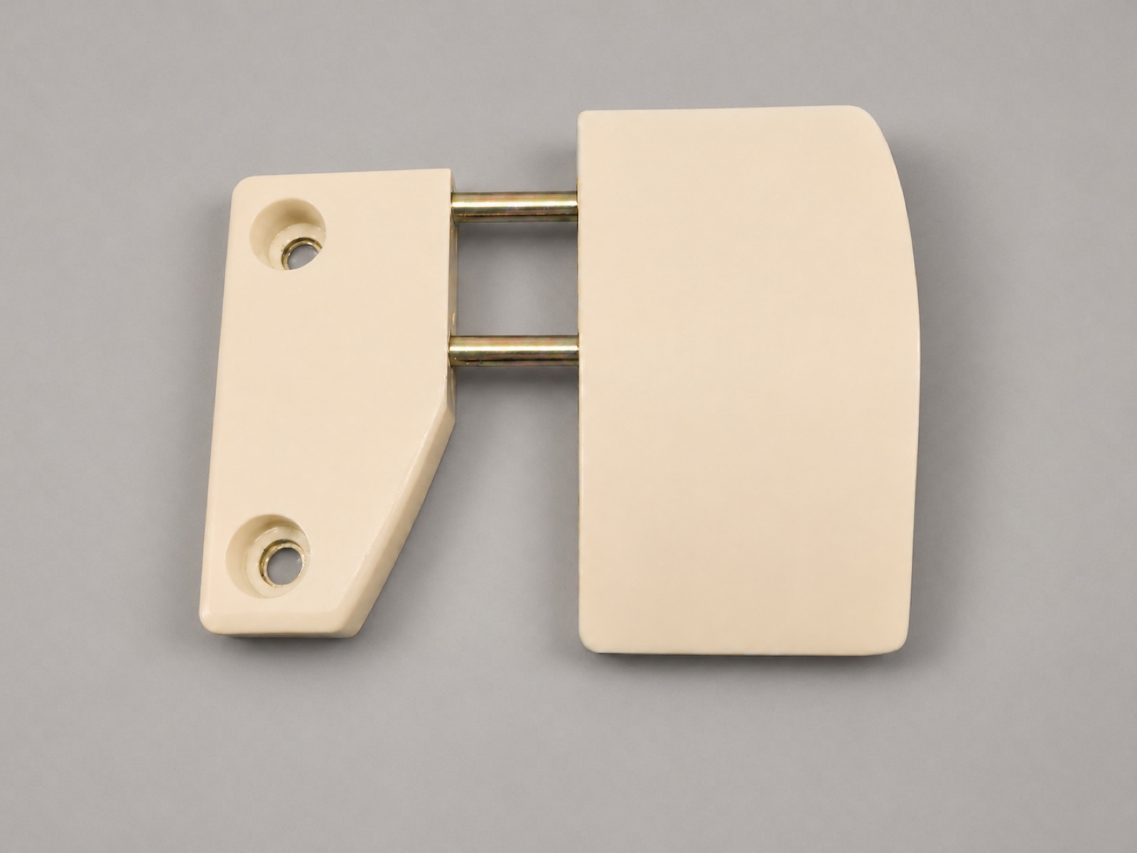
3. V2 — Two-Body Redesign

V2 keeps the V1 silhouette but splits the part along the deck edge. The new base plate is a thin mounting block that screws to the deck through the truck holes; the arc body is a separate piece that slides onto two 5 mm steel D-shafts press-fit into pockets on the base. The shafts have a machined flat that bears against the pocket wall to prevent rotation, and the pocket is sized with kerf compensation so the assembly is a tight friction fit by hand — no glue, no fasteners.
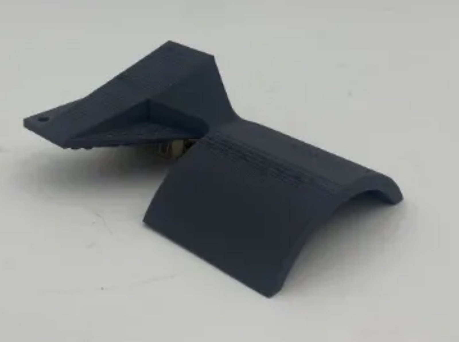
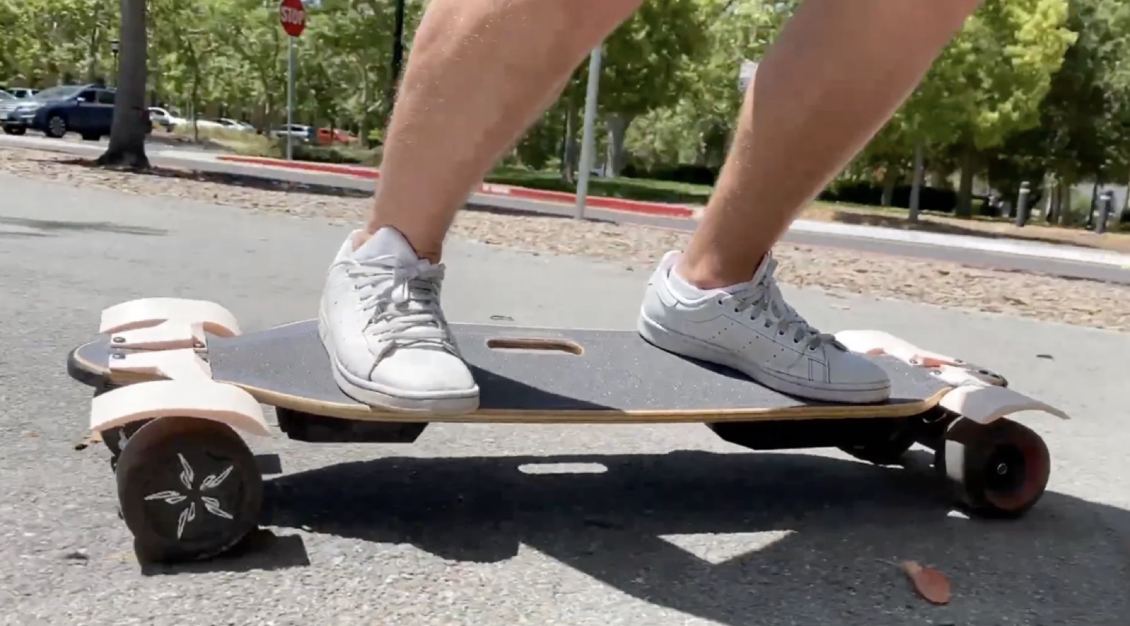
V2 components laid out: arc body, two steel D-shafts, and base body.
V2 components — arc body, two D-shafts, base body. Friction-fit assembly.
V2 partially assembled, top-down view with the two D-shafts spanning the gap between base and arc bodies.
Top-down view with the joint plane gapped open — the two D-shafts visible spanning between the bodies.

4. In the Wild

V2 mounted, ridden, water-tested. Fifteen+ rides in, the joint shows no slop, the bodies show no visible deformation, and water spray is consistently knocked down — the design works as intended.

V2 in motion — wheel turning, fender holding position, water deflected downward.
Second clip — different angle, same outcome.